More work on the landing gear

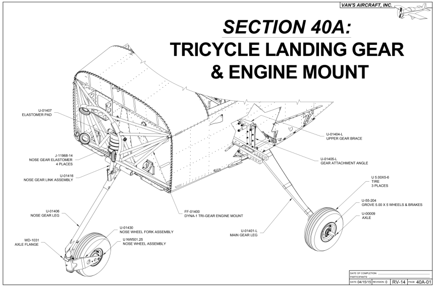
Primed the upper gear braces and gear attach angles.

img_4622


Split the nose wheel. Stuffed the tube into the tire and semi-inflated it. Put the tire and tube on the heels and bolted them back together.


Packed the bearings using my handy dandy bearing packer and reinstalled them into the wheel. Did a similar job on the main gear wheels. The main gear bearings were packed in a preservative grease. So I cleaned them with solvent dried them with compressed air, and repacked them with Aeroshell 22.


All three wheels assembled.

img_4629


I upgraded the nose gear wheel and axle to Matco. The axle has a bolt that keeps the axle from rotating. So I drilled a hole in the fork to accommodate.  I temporarily assembled the fork and axle to keep everything together.


I installed the gear attach angles and the upper gear braces. I loosely installed the gear attach bars. I should be able to just bolt the gear legs in and tighten them up.

img_4637


Next step is to clean the garage and relocate the fuselage from the basement. It won’t fit through the door once the gear is attached.


Today’s Time (hours): 8.0
Finish kit (hours): 175.0
Total Time (hours): 909.0


Began TricycleLanding Gear & Engine Mount (Section 40A)

Screen Shot 2020-04-25 at 8.11.49 PM


Separated the gear attachment angles on the band saw. This is a hefty chunk of aluminum angle. It took a good 15 minutes to get through it on my puny band saw.

img_4619


I decided that a new tool was in order to make the diagonal cuts. So I picked up a DeWalt Angle grinder and some cutoff wheels. It cut like butter. It took all of five minutes to get both angles cut.


Scuffed the angles as well as the other parts. Ready for priming tomorrow.


Today’s Time (hours): 2.0
Finish kit (hours): 167.0
Total Time (hours): 901.0


Finished wiring the fuse panel

Cut all the power wires to length and labeled each. Stripped each wire and terminated with a crimp on fuse holder. Had to buy yet another crimp tool for these… https://www.amazon.com/dp/B004P2VAVM/ref=cm_sw_r_sms_apip_atOw34QqkDCOo

I’m going to open a crimper museum when I’m done with the plane.


Inserted all of the terminated power wires into the Bussmann fuse block that I bought from Waytek.

img_4612


Mounted the fuse block and the Van’s power module kit, popped the fuses in and put the cover on.


I temporarily connected the battery and everything powered up with out incident or smoke. I still need to wire the GMU 11 in the left wing. Then I can plug the wing harnesses into the fuselage and test everything out. I also verified that PFD1 would power up from the IBBS. Very exciting to see all the avionics light up though.

img_4618


Today’s Time (hours): 8.0
Finish kit (hours): 165.0
Total Time (hours): 899.0


Finished wiring the panel

Wired the GSU 25 ADAHRS.

img_4597


Wired the G5 backup flight instrument.

img_4598


Pilot side complete. I still have a bit of tidying up and lacing to do. But everything is wired.


Terminated all of the ground lines to the ground block.

img_4601


Wired the PFD2 GDU 460.

img_4602


I still need to install the fuse panel and wire it up. I also need to wire the GMU 11 in the wing and reconfigure the connectors at the wing roots. Then the wiring will be complete.


Today’s Time (hours): 7.0
Finish kit (hours): 157.0
Total Time (hours): 891.0


Wired all the switches and the PFD-1

It’s been another busy week at work but managed to get in a few hours during the evenings and a bunch of time today.

Wired all the switches and routed all of the required power and ground wires as well as all the wires through the firewall for alternator, battery and starter relays, and magnetos.

img_4574


Reinstalled the PFD-1 GDU 460 and G5 backup instrument. I plumbed in the pitot, static, and AOA lines.

img_4594


Wired up the GDU 360. I was a real rats nest behind the panel so i used some temporary wire ties to keep things organized while I finish wiring the GSU 25 and the G5. Then I’ll secure everything properly and lace up the wire bundles.


I also realized that despite all of my wiring planning, I had accidentally omitted the GTP 59 temperature probe form the plan. I ran a shielded three-conductor cable from the left wing root to the panel.


Today’s Time (hours): 12.0
Finish kit (hours): 150.0
Total Time (hours): 884.0


Installed heater control cables

I ran out of heat shrink labels. So wiring came to a halt. I decided to install the cabin heat control cables yesterday. I figured it would be easier while the fuselage is still on its side.


I ran the pitot, AOA, and static lines through holes I drilled in the sub panel.

img_4571


This evening, I reinstalled the radio racks and instrument panel in preparation for wiring the GDU’s, G5, and panel switches.

img_4572


Today’s Time (hours): 4.0
Firewall Forward (hours): 4.0
Total Time (hours): 872.0


Finished wiring the GEA 24, GAD 29, and GAD 25

Made up harnesses for the TO/GA button and panel light dimmer switches. I mounted them back in the center panel and wired the corresponding connectors under the panel. I used micro molex connectors to make the connections.


I received the stranded thermocouple wire I ordered from McMaster Carr. SO I was able to finish wiring up the GEA 24.


I wired up the GAD 29.

img_4554


I wired up the GAD 27.


Making progress. Glad I made this wiring list.  It’s been super helpful as a reference and to keep track of my progress. The terminations highlighted in green are complete.

img_4563


Today’s Time (hours): 10.0
Finish Kit (hours): 138.0
Total Time (hours): 868.0


Wiring Continues

Haven’t posted in a while but making steady progress.

Made a wiring harness for the TO/GA switch.

img_4539


Wired up the canopy harness.

img_4542


Relocated the GAD 27, GAD 29, and GEA 24.


Made up two of the four connectors for the GEA 24. Had to re-order the thermocouple wire for the EGT and CHT connections. I accidentally ordered solid wire instead of stranded. Connecting the engine to the airframe, there’s enough motion in those wires that I wasn’t comfortable using the solid wire. It probably would take long for it to work harden and break.


SO. MANY. WIRES!!!

img_4548

So glad i borrowed Jared’s engine stand rotisserie. I can’t imagine doing this with the airframe upright.


Today’s Time (hours): 8.0
Finish Kit (hours): 128.0
Total Time (hours): 858.0


Wired the radio stack

Made my first CAN Bus daisy chain termination for the GTR 200B com radio.


Finished wiring the COM radio connector.


Terminated the antenna cables with BNC connectors for the transponder and com radio and a TNC connector for the GPS.


Made up the connector for the GMC 507 autopilot control. Pretty simple… Power, Ground and CAN bus.

img_4532


Installed the com radio tray and the transponder and GPS trays that I had pre-wired. I routed and tied all the wires.


Today’s Time (hours): 8.0
Finish Kit (hours): 120.0
Total Time (hours): 850.0


Progress continues on wiring

I’ve neglected to post over the past week. Been a busy week at work. I have made some good progress though.

I vinyl-wrapped the fuse block panel and screwed the fuse block into it. I made a bus bar from a strip of copper to tie together the upper and lower buses of the fuse block.


I drilled some system holes through the left seat ribs, installed snap bushings, and ran the pitot and AOA lines from the wing root to the panel.


Drilled a couple of system holes in the lower sub-panel. Routed the the wires for the battery backup. Terminated the grounds for the the IBBS and the IBBS master switch.


Made up the connectors for the GTX 45R transponder and the GTN 625 GPS. I also started on the GTR 200B COM radio but didn’t get a picture.


Today’s Time (hours): 6.0
Finish Kit (hours): 112.0
Total Time (hours): 842.0