Installed heater control cables

I ran out of heat shrink labels. So wiring came to a halt. I decided to install the cabin heat control cables yesterday. I figured it would be easier while the fuselage is still on its side.


I ran the pitot, AOA, and static lines through holes I drilled in the sub panel.

img_4571


This evening, I reinstalled the radio racks and instrument panel in preparation for wiring the GDU’s, G5, and panel switches.

img_4572


Today’s Time (hours): 4.0
Firewall Forward (hours): 4.0
Total Time (hours): 872.0


Finished wiring the GEA 24, GAD 29, and GAD 25

Made up harnesses for the TO/GA button and panel light dimmer switches. I mounted them back in the center panel and wired the corresponding connectors under the panel. I used micro molex connectors to make the connections.


I received the stranded thermocouple wire I ordered from McMaster Carr. SO I was able to finish wiring up the GEA 24.


I wired up the GAD 29.

img_4554


I wired up the GAD 27.


Making progress. Glad I made this wiring list.  It’s been super helpful as a reference and to keep track of my progress. The terminations highlighted in green are complete.

img_4563


Today’s Time (hours): 10.0
Finish Kit (hours): 138.0
Total Time (hours): 868.0


Began wiring the panel

I’ve spent quite a bit of time researching and documenting a plan to make the wiring easy. I complied a list of wiring nodes in a spreadsheet that I can use as a checklist to work my way through the project. You can see my work here… Wiring Plan

Didn’t actually wire anything today but rather did a lot of the prep work. I fabricated a center panel that will hold the fuse block in the center pedestal. I purchased the power panel option from Van’s which included the sheet metal for the center console. I purchased the 32 position Busman fuse block from Waytek.


Prepped everything up and painted it to match the interior.

img_4480


Removed all of the avionics and the panels. I probably could have left the stuff mounted to the sub panel and left the panels in place. But when I had mounted everything with black oxide steel screws and subsequently learned that they would rust over time. So I purchased black oxide stainless replacements. This was the most opportune time to replace them all.


I installed a ground block being careful to remove all the paint and scuff up the sub-panel to ensure a good electrical connection. I re-mounted the backup battery, the GAD 27, GAD 29, and GEA 24 to the sub panel.


I drilled a couple of new wire holes through the bottom of the stand-offs and installed snap bushings. The original holes interfered with the GTX and the switches in the bottom of the middle panel.

img_4481


Today’s Time (hours): 8.0
Finish Kit (hours): 106.0
Total Time (hours): 836.0


Cut the pilot-side instrument panel

I used the fly cutter in the drill press to cut the round hole for the G5, I drilled small pilot holes for all the switches and the corners of the GDU 460 cutout. I final drilled all the holes with a step drill. Then cut the hole for the GDU with a Dremel and a cut-off wheel. Actually went through several cut-off wheels. That’s some thick aluminum. Used a file to clean everything up and tweak to fit. Then I painted the back to match the interior. I screwed the G5 mount in place. I drilled the screw holes for the GDU mounting bracket. Then screwed it to the firewall and match drilled the rivet holes, counter sunk the holes and riveted the bracket to the panel.


Mounted all the avionics and switches in the panel and mounted the panel in the plane.

img_4038


Today’s Time (hours): 4.0
Options and Miscellanea Time (hours): 22.0
Total Time (hours): 705.0


Began work on panel

Mocked up the center panel in plexi. Used the Dremel with a cutoff wheel to make the cuts.


Mocked up the pilot-side panel in plexi. I used a fly cutter in the drill press to cut the 3 1/8″ hole for the G5. I centered the ignition/starter switch under the G5 and placed the electronic ignition power switches above the ignition switch. I’ll only need one for now as the engine came with one mag and one P-mag. But I’m making accommodations to switch out the mag for a second p-mag in the future. I grouped the switches along the bottom into logical groupings based upon function. Master and Aux Batt on the left, then boost pump, then lights (landing, nav, strobe), then pitot heat and defroster. I mounted a momentary push button in the center panel right above where the throttle will be. This will be for the AP’s TOGA function.


I laid out the final design on the actual metal blank. I made a couple of alterations. I took the time to better align the G5, Ignition, and P-mag switches. I also moved the row of switches below the GDU downward by 1/4″

img_4027


Committed the center panel to metal. I used the plexi as a template and drew the cutouts onto the panel. Then I cut it with the Dremel. I fit and fiddled with it using files and many trial fittings. I used files to cut small notches for the GTN’s side guides and for the pall on the bottom of the GTR 200 to make it easier to insert and remove. I’ll likely add a panel light dimmer switch to the center panel at some point. I just haven’t acquired the switch yet.

img_4028


Today’s Time (hours): 6.0
Avionics Time (hours): 18.0
Total Time (hours): 693.5


Started mounting avionics

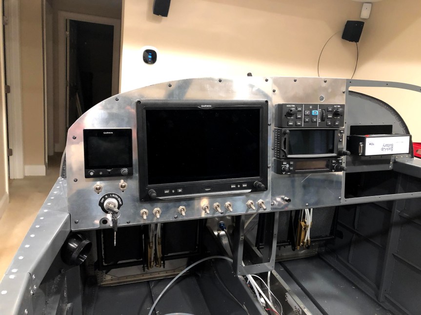
Made some trial panels from plastic. I’ll use these to lay out the panel and make sure everything fits before I start cutting metal. I’f I do this properly and everything works out, I should be able to use these as templates to lay out the actual metal panels.

img_4011


Temporarily mounted the GAD27 (ARINC), GAD29 (electrical device controller), and GEA 24 engine indication system. I mounted the GEA 24 directly to the sub panel. I made a stand-off mount for the GAD 27 using some aluminum sheet and some aluminum tubing. This let me “stack” the two boxes fore and aft. This was the same approach that Jared took in his plane. So I can’t claim credit. I also mounted the TCW integrated backup battery system. I fit the boxes, drilled the sub panel, and attached the boxes with temporary hardware I had lying around. I’ll get the proper hardware this week.


I fabricate a doubler to mount the WaaS GPS antenna. I cut a piece of aluminum to sive, laid out the holes for the antenna and rivets. I match drilled the empennage top skin to the doubler. I dimpled the doubler, riveted nut plates to it, and primed with SEM rattle can. I dimpled the top skin with the pop rivet dimple dies. I riveted the doubler to the inside of the skin and screwed the antenna in place with the supplied hardware.


Started fitting the radio stack. I used a digital level and shimmed up the front of the radios so that the were perpendicular to the panel. Determined that I need to enlarge the center opening in the sub panel in order to accommodate the radios without blocking the canopy release. Even then, everything barely fits.

I picked up a vibratory cutter and a flush cutting blade. I’ll use this to cut the sub panel tomorrow.


Today’s Time (hours): 6.0
Options and Miscellanea Time (hours): 7.0
Total Time (hours): 682.5


Installed Canopy Decks and Panel Frame

Laid a bead of tank sealant to fill the gap between the side skin, longeron, and canopy deck. Then I clecoed and riveted the canopy decks in place.


Riveted the wire supports to the bottoms of the panel standoffs.

img_3903


Clecoed the panel in place. I couldn’t rivet it because I ran out of K1000-06 nut plates. Ordered from Spruce.


Today’s Time (hours): 2.0
Fuselage Time (hours): 191.0
Total Time (hours): 645.5