
Received the Finishing kit and Firewall Forward kit this morning. Spent the whole day inventorying. There are a shitload of parts in these kits.

| Today’s Time (hours): | 7.0 |
| Finish Kit Time (hours): | 7.0 |
| Total Time (hours): | 700.5 |
Received the Finishing kit and Firewall Forward kit this morning. Spent the whole day inventorying. There are a shitload of parts in these kits.
| Today’s Time (hours): | 7.0 |
| Finish Kit Time (hours): | 7.0 |
| Total Time (hours): | 700.5 |
Mocked up the center panel in plexi. Used the Dremel with a cutoff wheel to make the cuts.


Mocked up the pilot-side panel in plexi. I used a fly cutter in the drill press to cut the 3 1/8″ hole for the G5. I centered the ignition/starter switch under the G5 and placed the electronic ignition power switches above the ignition switch. I’ll only need one for now as the engine came with one mag and one P-mag. But I’m making accommodations to switch out the mag for a second p-mag in the future. I grouped the switches along the bottom into logical groupings based upon function. Master and Aux Batt on the left, then boost pump, then lights (landing, nav, strobe), then pitot heat and defroster. I mounted a momentary push button in the center panel right above where the throttle will be. This will be for the AP’s TOGA function.


I laid out the final design on the actual metal blank. I made a couple of alterations. I took the time to better align the G5, Ignition, and P-mag switches. I also moved the row of switches below the GDU downward by 1/4″

Committed the center panel to metal. I used the plexi as a template and drew the cutouts onto the panel. Then I cut it with the Dremel. I fit and fiddled with it using files and many trial fittings. I used files to cut small notches for the GTN’s side guides and for the pall on the bottom of the GTR 200 to make it easier to insert and remove. I’ll likely add a panel light dimmer switch to the center panel at some point. I just haven’t acquired the switch yet.

| Today’s Time (hours): | 6.0 |
| Avionics Time (hours): | 18.0 |
| Total Time (hours): | 693.5 |
Picked up a Dremel vibratory cutter and used it to enlarge the center cut-out in the sub panel in order to accommodate my radio stack. I was pleased with the new tool. Cut like butter. I finished it off with a file and some sand paper.

I mounted all of the radio trays into the central radio rack. This was fiddly work. I had to slot several of the holes that I drilled in order to get everything to line up perfectly. I used #6 flat head screws, washers, and nylock nuts to hold everything in place. I used the trays themselves as drilling templates. I used a long #40 drill bit to make pilot holes and then drilled to size from the outside of the panel standoffs. I used an extra long screw driver to set the screws.
The placement of the canopy release handle presented a challenge. I had to get everything mounted low enough so that the top of the AP controller didn’t interfere with the hole for the release. I squeezed everything in with less than 1/4″ clearance.


I’ll probably need to uninstall all of the trays to make up the connectors but.
| Today’s Time (hours): | 5.0 |
| Options and Miscellanea Time (hours): | 12.0 |
| Total Time (hours): | 687.5 |
Made some trial panels from plastic. I’ll use these to lay out the panel and make sure everything fits before I start cutting metal. I’f I do this properly and everything works out, I should be able to use these as templates to lay out the actual metal panels.

Temporarily mounted the GAD27 (ARINC), GAD29 (electrical device controller), and GEA 24 engine indication system. I mounted the GEA 24 directly to the sub panel. I made a stand-off mount for the GAD 27 using some aluminum sheet and some aluminum tubing. This let me “stack” the two boxes fore and aft. This was the same approach that Jared took in his plane. So I can’t claim credit. I also mounted the TCW integrated backup battery system. I fit the boxes, drilled the sub panel, and attached the boxes with temporary hardware I had lying around. I’ll get the proper hardware this week.


I fabricate a doubler to mount the WaaS GPS antenna. I cut a piece of aluminum to sive, laid out the holes for the antenna and rivets. I match drilled the empennage top skin to the doubler. I dimpled the doubler, riveted nut plates to it, and primed with SEM rattle can. I dimpled the top skin with the pop rivet dimple dies. I riveted the doubler to the inside of the skin and screwed the antenna in place with the supplied hardware.


Started fitting the radio stack. I used a digital level and shimmed up the front of the radios so that the were perpendicular to the panel. Determined that I need to enlarge the center opening in the sub panel in order to accommodate the radios without blocking the canopy release. Even then, everything barely fits.
I picked up a vibratory cutter and a flush cutting blade. I’ll use this to cut the sub panel tomorrow.


| Today’s Time (hours): | 6.0 |
| Options and Miscellanea Time (hours): | 7.0 |
| Total Time (hours): | 682.5 |
Today was a bit of a shit show. Last night I worked on the roll bar after a fun day of flying with Jared, Wes, and Scott. Realized that I didn’t have enough AN426AD4-5 rivets to complete the roll bar. So I put in an order with spruce. I need a bunch of stuff anyway. Drove down there this morning and picked everything up. So far so good.
Here’s a picture of Wes’ beautiful RV-7 on the way back from NC yesterday.

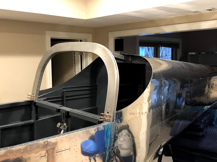
Last night I riveted the brackets to the roll bar brace. I temporarily mounted the left and right forward roll bar parts to the fuselage as a jig to rivet the splice plate. Then did the same for the aft half of the roll bar. Then I clecoed the forward and aft halves together with the inboard and outboard straps and window shims and final drilled everything. I deburred all the parts and countersunk the ones that needed countersinking. I riveted the forward roll bar assembly to the inboard strap with the AN470 rivets called out in the plans. That’s when I realized that I didn’t have enough AN426AD4-3 rivets to do the next step which was to rivet the outboard strap.


Segue to today… Went to Spruce. Got the rivets and a bunch of other goodies… Ignition switch and toggle switches. Then back to work… I riveted the outboard strap to the forward roll bar assembly. I joined it up with the aft half and used the LP and CS blind rivets to assemble the whole thing. I also riveted the bushings and doubles in place on the aft sections.


And then… Disaster! The little arrow in the picture is pointing the wrong way. I misread the plans last night. I had to drill out three quarters of the hundred or so rivets holding this whole thing together so that I could reorient the outboard strap to face the proper direction to properly mate to the roll bar brace. I lost about 2.5 hours to this. Plus a lot of frustration. Stupid mistake.

Once I got through reassembling the roll bar, I was able to mount it on the fuselage and match drill the bases and get everything riveted in place. But to add insult to injury, I’m now short a number of CS4-4 and LP4-3 rivets due to the error. So I can’t actually finish the section. But I did get as far as I could and placed an order with Vans for the rivets. There’s only about half an hour of work to finish it up once I have the rivets. I’ll move on to something else but it sure would have been nice to have been able to paint it up this weekend and call the Fuselage complete.
| Today’s Time (hours): | 6.0 |
| Fuselage Time (hours): | 221.0 |
| Total Time (hours): | 676.5 |
Checked the fore and aft travel of the control system with a digital level using the top of the cover rib as a reference. Filed the control column bracket stops until I achieved the specified range of travel in each direction and the control column hit the stops on both side simultaneously.


Installed the control sticks and measured the distance between them. Thy were spot on so I guess I measured the control stick tie rod correctly. No adjustment necessary.


I double checked that I torqued all the hardware properly and marked everything with torque seal. I decided to wait on installing that aft elevator push tube until I reinstall the tail feathers at the airport.
| Today’s Time (hours): | 1.0 |
| Fuselage Time (hours): | 215.0 |
| Total Time (hours): | 670.5 |
Primed all the parts.

Bolted the elevator idle arm in place.

Assemble the stick link pushrod.

Riveted the elevator pushrod ends into the rods and added the rod end bearings.


Bolted the forward push tube to the control column.

Put together the elevator bell crank assembly. riveted the bell crank halves together with the flange bearing in the middle. Machine countersunk the the nut plate holes in the bell crank bracket and riveted in the nut plates. Bolted the bell crank angles to the bell crank and then to the bell crank bracket. Machine countersunk and riveted together the yaw servo bracket. The match drilled it to the the fuselage and installed the bell crank assembly together with the mid elevator push tube, pitch servo bracket, and yaw servo bracket.


Connected the forward and mid push tubes to the idler arm.

Final rilled the control stick bases to the control sticks. The installed the bases into the control column. Bolted the stick link to the right hand stick base. I’ll bolt up the other side after I’ve checked the alignment of the sticks.

| Today’s Time (hours): | 6.0 |
| Fuselage Time (hours): | 214.0 |
| Total Time (hours): | 669.5 |
Primed all the roll over structure parts.

| Today’s Time (hours): | 1.0 |
| Fuselage Time (hours): | 208.0 |
| Total Time (hours): | 663.5 |
Installed flap position sensor.

| Today’s Time (hours): | 1.0 |
| Options and Miscellanea (hours): | 1.0 |
| Total Time (hours): | 662.5 |
Masked off and painted the sticks.


| Today’s Time (hours): | 1.0 |
| Fuselage Time (hours): | 207.0 |
| Total Time (hours): | 661.5 |
