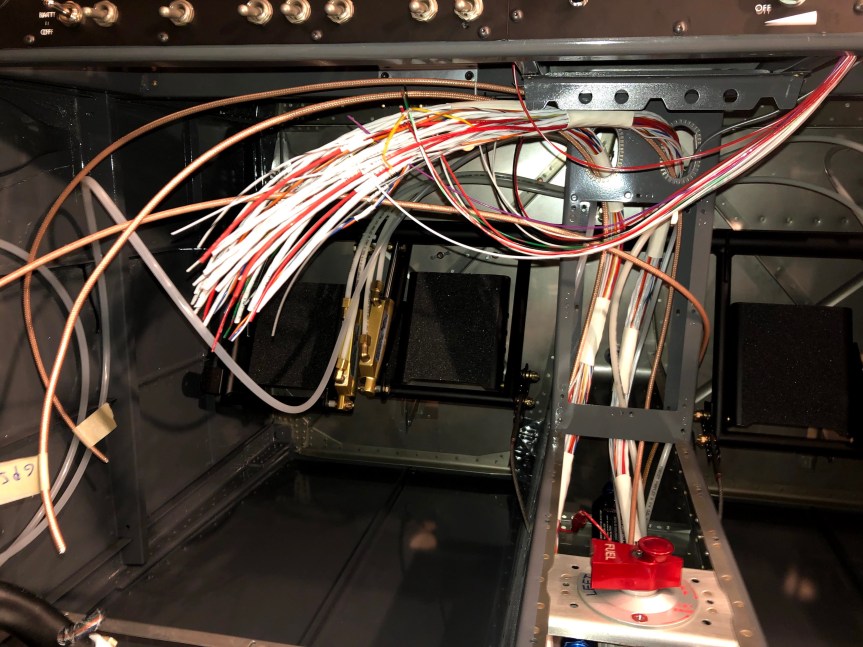
Ran the right side harness from the aft fuselage bulkhead all the way to the panel and pulled the wing portion of the harness out through the side skin and fastened the ground wires.
The harness from Van’s was designed for the Garmin GMU 22 magnetometer. Garmin has since come out with the GMU 11 and that is what was included in my avionics package. The GMU 11 broadcasts heading information on the CAN bus rather than the RS-232/RS-485 point-to-point topology. This requires some modifications to the harness. I teased out the 2-conductor shielded cable that carries the CAN bus from the autopilot servos in the tail to the instrument panel from the harness and rerouted it to the left wing where the GMU 11 is mounted. I will repurpose a couple of connector pins in the wing harness for this and make up a harness to wire the GMU 11 to the wing harness connector (P403). I can then reuse one of the the 2-conductor shielded cables from the P403 connector to the panel to bring the CAN bus from the left wing to the panel. I’ll use the four conductor cable to bring power, e-bus power, and ground to the GMU 11 from the power bus and ground block. All in all this is a huge pain in the ass and required a lot of head scratching. I wish Van’s kept up with the state of the Garmin offerings. Even if they can’t update the harness, at least cover it in the instructions.
I managed to get all of th snap bushings in place. I added a few tie wraps as well. I’m thinking I’d like the harness to be more secure between the spar and the aft fuselage bulkhead. Looks like there’s opportunity for the elevator push tubes to rub the harness. I’ll work on that once I’ve got all the wires run.
I haven’t run the control stick harness through the cover ribs yet. Looks like the holes require some filing to fit the connectors through. Thanks again Van’s. Perhaps the plans could have called this out prior to installing the ribs. Very tight spaces to work in. That will be tomorrow’s project.
| Today’s Time (hours): |
3.0 |
| Options and Miscellanea Time (hours): |
41.0 |
| Total Time (hours): |
730.0 |