Wiring Continues

Ran the right harness up to the co-pilot’s control stick. This required filing out a number of holes along the way to enable the connector to fit through.  I also ran the wires for the GPS, transponder, and com radio.


Today’s Time (hours): 3.0
Options and Miscellanea Time (hours): 44.0
Total Time (hours): 733.0


Began work on Common Fuselage Harness (Section 55)

Screen Shot 2020-01-11 at 10.07.19 PM

Ran the right side harness from the aft fuselage bulkhead all the way to the panel and pulled the wing portion of the harness out through the side skin and fastened the ground wires.

The harness from Van’s was designed for the Garmin GMU 22 magnetometer. Garmin has since come out with the GMU 11 and that is what was included in my avionics package. The GMU 11 broadcasts heading information on the CAN bus rather than the RS-232/RS-485 point-to-point topology. This requires some modifications to the harness. I teased out the 2-conductor shielded cable that carries the CAN bus from the autopilot servos in the tail to the instrument panel from the harness and rerouted it to the left wing where the GMU 11 is mounted. I will repurpose a couple of connector pins in the wing harness for this and make up a harness to wire the GMU 11 to the wing harness connector (P403). I can then reuse one of the the 2-conductor shielded cables from the P403 connector to the panel to bring the CAN bus from the left wing to the panel. I’ll use the four conductor cable to bring power, e-bus power, and ground to the GMU 11 from the power bus and ground block. All in all this is a huge pain in the ass and required a lot of head scratching. I wish Van’s kept up with the state of the Garmin offerings. Even if they can’t update the harness, at least cover it in the instructions.

I managed to get all of th snap bushings in place. I added a few tie wraps as well. I’m thinking I’d like the harness to be more secure between the spar and the aft fuselage bulkhead. Looks like there’s opportunity for the elevator push tubes to rub the harness. I’ll work on that once I’ve got all the wires run.


I haven’t run the control stick harness through the cover ribs yet. Looks like the holes require some filing to fit the connectors through. Thanks again Van’s. Perhaps the plans could have called this out prior to installing the ribs. Very tight spaces to work in. That will be tomorrow’s project.


Today’s Time (hours): 3.0
Options and Miscellanea Time (hours): 41.0
Total Time (hours): 730.0


Autopilot Yaw Servo (Section 58)

Screen Shot 2020-01-11 at 10.33.51 PM


Removed the stock servo arm and attached the Garmin tiller arm to the servo. Installed the servo into the fuselage. Still need to attach the bridle cables to the rudder cables but can’t do that Until the rudder is mounted. So I’ll wait and do this at the airport when I reassemble the tail.


Today’s Time (hours): 2.0
Options and Miscellanea Time (hours): 38.0
Total Time (hours): 727.0


Garmin Autopilot Servos (Section 56)

Screen Shot 2020-01-11 at 10.35.57 PM


Installed the pitch servo.

img_4084


When I got everything put together, I noticed that the forward jam nut on the pushrod was just barely interfering with the elevator bellcrank. So I added and extra washer between the rod end bearing and the bellcrank. This seems to have resolved the issue. I emailed Van’s just to make sure this doesn’t introduce any other problems.

img_4082


Today’s Time (hours): 2.0
Options and Miscellanea Time (hours): 36.0
Total Time (hours): 725.0


Installed ACK ELT (Section 53)

Screen Shot 2020-01-11 at 10.37.22 PM


Installed battery into audio alerter. Note to self: Battery expires March 2028. Installed the alerter under the nose rib of the vertical stabilizer.


Mounted the ELT to the empennage.


Installed the DIN connector to the empennage wiring harness and connected to the ELT.


Wire tied everything up and got pics of the ELT’s hex code so that I can register it later. Also noted the ELT Battery expiration date of 1/25/2024.


Installed a Duracell 28L battery (Expires March 2028) into the RCPI and installed the RCPI into the co-pilot’s panel.

img_4080


Today’s Time (hours): 2.0
Options and Miscellanea Time (hours): 34.0
Total Time (hours): 723.0


Finished panel and mounting avionics

Uninstalled all the avionics and removed the panels. I covered the panels with 3M 2080 matte black vinyl wrap. This is the stuff they use to wrap cars. Then I created the panel labels using a Cricut vinyl cutter. Spent a lot of time fiddling with the tiny letters to get them onto the panel but eventually figured it out. I used transfer tape to transfer the cut vinyl to the panel then weeded out the excess vinyl in place on the panel rathe than the conventional approach of weeding the vinyl before applying the transfer tape. The letters were just too small and would move around or fall off the backing when I tried it that way.


Got everything reinstalled in the airplane to see how it looked. I’m happy with the way it came out. Although I’m having second thoughts about the canopy release label. Might be a bit over the top. The intent was to make sure any curious passengers were left with the impression that if they pulled it, something serious is going to happen. May tone it down at some point but for now it’s done.

Now I need to wire everything up. Perhaps later. I’ll be finishing up a couple of small projects tomorrow and then I’ll be starting in on the finishing kit next weekend.

img_4058


Today’s Time (hours): 7.0
Options and Miscellanea Time (hours): 32.0
Total Time (hours): 721.0


Cut the co-pilot-side panel

Same drill as the pilot side…  Lay everything out, drill pilot holes, final drill with step drill, cut with Dremel, deburr, machine countersink, paint, rivet, and bam! We have a panel.


Mounted the GDU and the ELT switches to the panel and mounted the panel in the plane.

img_4046


Next, I’m going to cover the panel in flat black vinyl. I’m also thinking about adding a carbon monoxide detector beneath the ELT buttons.

Today’s Time (hours): 3.0
Options and Miscellanea (hours): 25.0
Total Time (hours): 708.0


Cut the pilot-side instrument panel

I used the fly cutter in the drill press to cut the round hole for the G5, I drilled small pilot holes for all the switches and the corners of the GDU 460 cutout. I final drilled all the holes with a step drill. Then cut the hole for the GDU with a Dremel and a cut-off wheel. Actually went through several cut-off wheels. That’s some thick aluminum. Used a file to clean everything up and tweak to fit. Then I painted the back to match the interior. I screwed the G5 mount in place. I drilled the screw holes for the GDU mounting bracket. Then screwed it to the firewall and match drilled the rivet holes, counter sunk the holes and riveted the bracket to the panel.


Mounted all the avionics and switches in the panel and mounted the panel in the plane.

img_4038


Today’s Time (hours): 4.0
Options and Miscellanea Time (hours): 22.0
Total Time (hours): 705.0


Began work on panel

Mocked up the center panel in plexi. Used the Dremel with a cutoff wheel to make the cuts.


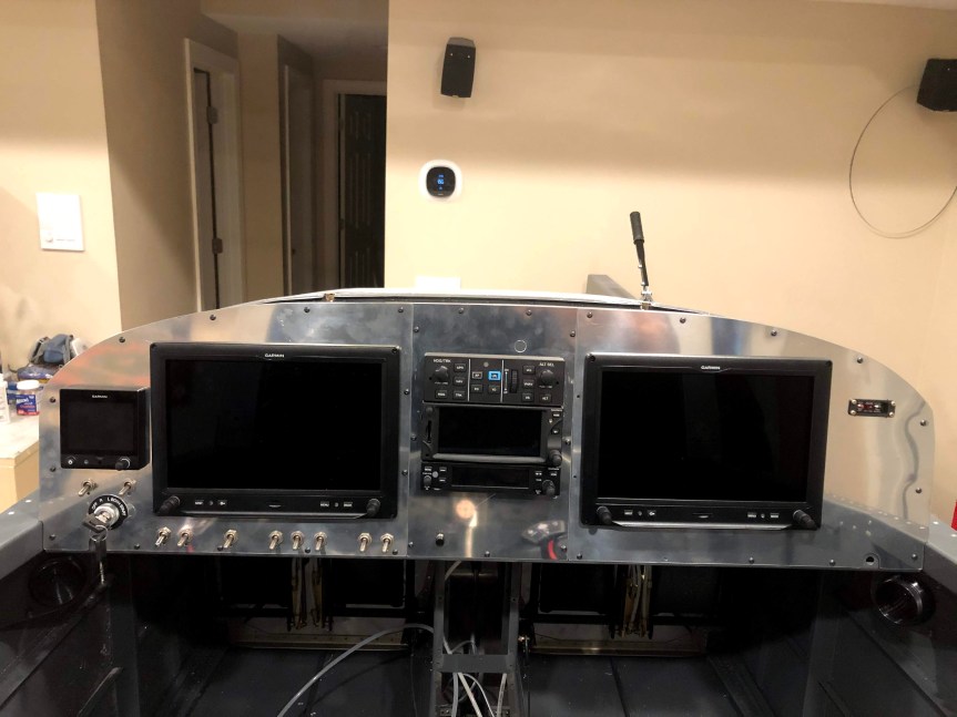
Mocked up the pilot-side panel in plexi. I used a fly cutter in the drill press to cut the 3 1/8″ hole for the G5. I centered the ignition/starter switch under the G5 and placed the electronic ignition power switches above the ignition switch. I’ll only need one for now as the engine came with one mag and one P-mag. But I’m making accommodations to switch out the mag for a second p-mag in the future. I grouped the switches along the bottom into logical groupings based upon function. Master and Aux Batt on the left, then boost pump, then lights (landing, nav, strobe), then pitot heat and defroster. I mounted a momentary push button in the center panel right above where the throttle will be. This will be for the AP’s TOGA function.


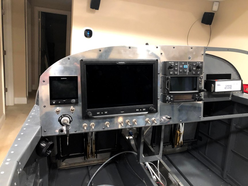
I laid out the final design on the actual metal blank. I made a couple of alterations. I took the time to better align the G5, Ignition, and P-mag switches. I also moved the row of switches below the GDU downward by 1/4″

img_4027


Committed the center panel to metal. I used the plexi as a template and drew the cutouts onto the panel. Then I cut it with the Dremel. I fit and fiddled with it using files and many trial fittings. I used files to cut small notches for the GTN’s side guides and for the pall on the bottom of the GTR 200 to make it easier to insert and remove. I’ll likely add a panel light dimmer switch to the center panel at some point. I just haven’t acquired the switch yet.

img_4028


Today’s Time (hours): 6.0
Avionics Time (hours): 18.0
Total Time (hours): 693.5


Mounted Radios

Picked up a Dremel vibratory cutter and used it to enlarge the center cut-out in the sub panel in order to accommodate my radio stack. I was pleased with the new tool. Cut like butter. I finished it off with a file and some sand paper.

img_4012


I mounted all of the radio trays into the central radio rack. This was fiddly work. I had to slot several of the holes that I drilled  in order to get everything to line up perfectly. I used #6 flat head screws, washers, and nylock nuts to hold everything in place. I used the trays themselves as drilling templates. I used a long #40 drill bit to make pilot holes and then drilled to size from the outside of the panel standoffs. I used an extra long screw driver to set the screws.

The placement of the canopy release handle presented a challenge. I had to get everything mounted low enough so that the top of the AP controller didn’t interfere with the hole for the release. I squeezed everything in with less than 1/4″ clearance.


I’ll probably need to uninstall all of the trays to make up the connectors but.

Today’s Time (hours): 5.0
Options and Miscellanea Time (hours): 12.0
Total Time (hours): 687.5